Raspberry Pi 5 IMX519 Camera Setup
This guide explains how to connect and configure the Arducam IMX519 camera on the Raspberry Pi 5, and how to test still captures using shell scripts.
Tested Hardware
- Raspberry Pi 5 – 8GB RAM
- Arducam IMX519 Camera Module, SKU: B0371 x 2
- CSI 22-to-22-pin Ribbon Cable (15 cm or 20 cm recommended) x 2
- Raspberry Pi Official Power Supply (5V/3A or higher, 27 W PSU recommended)
- microSD Card 16 GB with Raspberry Pi OS Lite (64-bit) installed
Initial setup steps for Raspberry Pi OS can be found in the Raspberry Pi Documentation.
1. Hardware Connection
For camera connection we followed the Arducam Quick Start Guide for Hardware Setup.
Camera Connection
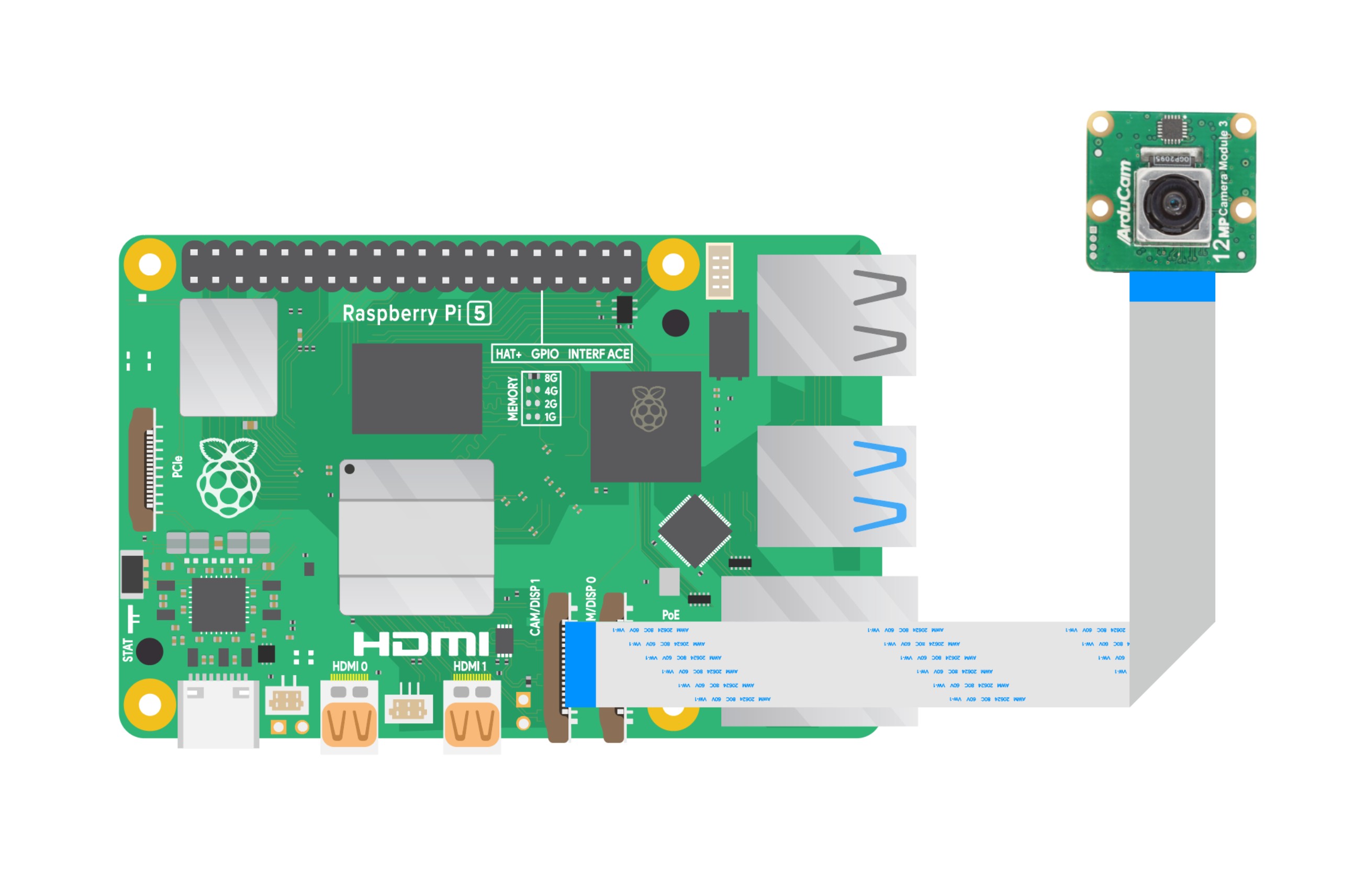
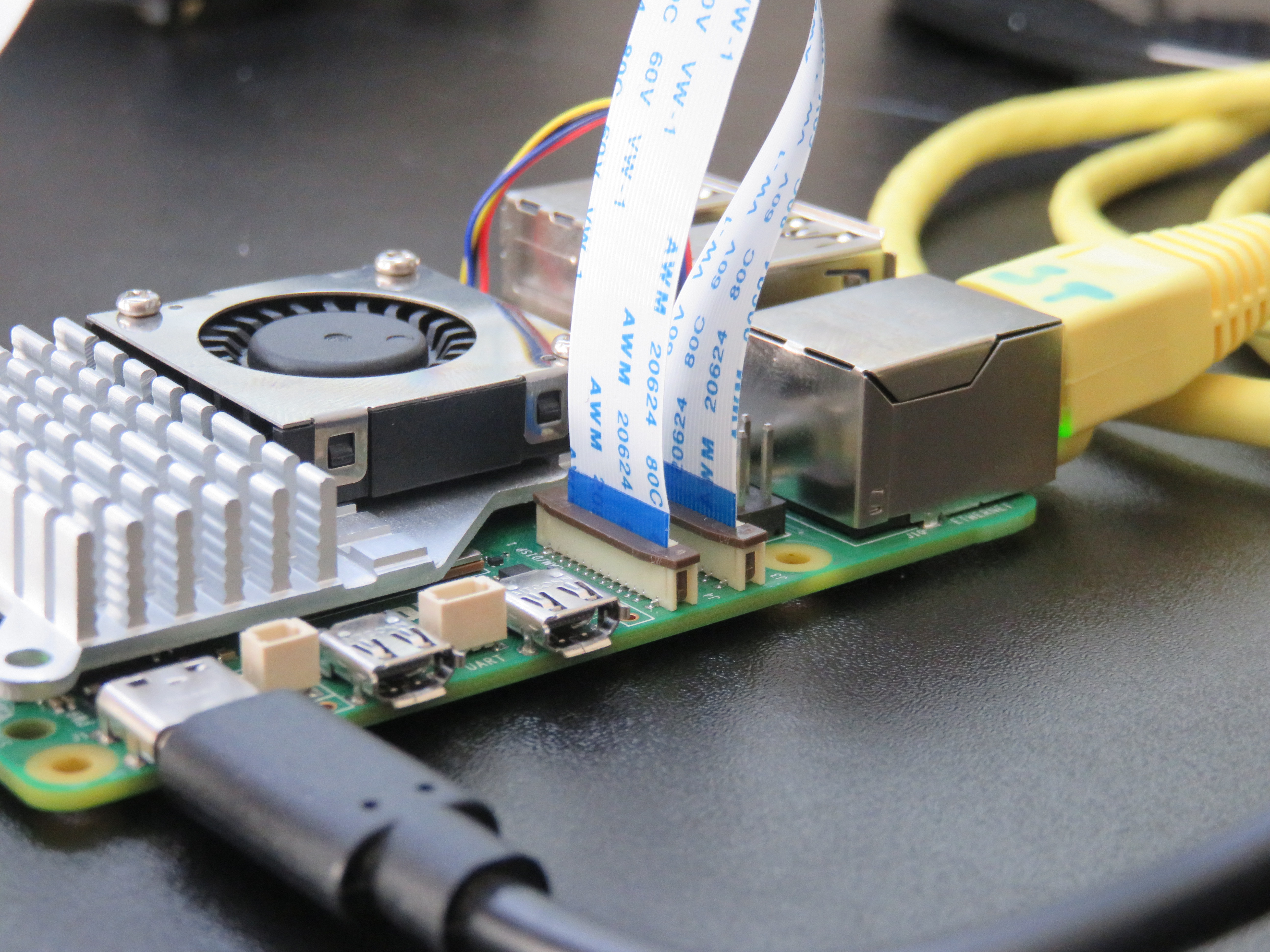
The actual camera connection looks like this:

Make sure the ribbon cable is properly seated in the connector with the blue stiffener facing outward (toward the Ethernet port) and the metal contacts facing inward toward the board.
Dual Camera Connection on Raspberry Pi 5
The Raspberry Pi 5 includes two CSI connectors labeled CAM0 and CAM1. Connect one camera to each port using 22-pin ribbons.
Both ports require the cable’s metal contacts to face the Ethernet port.
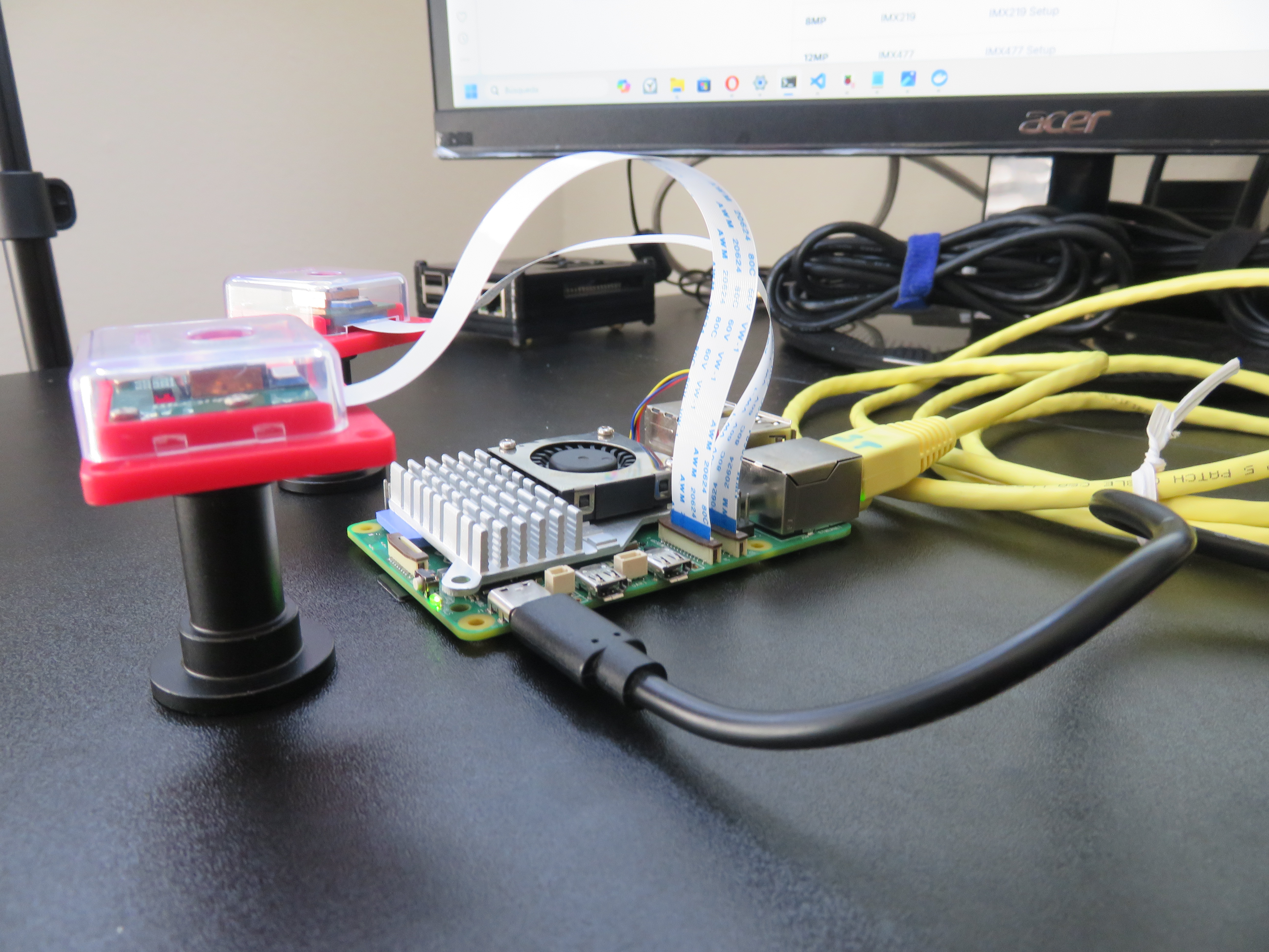
Final Assembly
After connecting the cameras, ensure everything is securely in place. Attach any necessary heatsinks or cooling solutions, and insert the microSD card with Raspberry Pi OS installed. Finally, connect the power supply to boot up the Raspberry Pi 5. Attach peripherals (keyboard, mouse, monitor) or set up SSH for headless operation.
2. Software Setup
For this step, we followed the Arducam IMX519 Software Setup Guide, specifically the instructions for Raspberry Pi Bullseye OS 6.1.21 and Later / Bookworm OS.
Note on software stacks: Raspberry Pi’s official
rpicam-appsare generally preferred for Pi 5, but in our tests they did not successfully detect the IMX519. The method below, using Arducam’s packages, worked reliably. Other setups may succeed withrpicam-apps, but this guide documents the tested path.
Step 1: Download the bash script
wget -O install_pivariety_pkgs.sh https://github.com/ArduCAM/Arducam-Pivariety-V4L2-Driver/releases/download/install_script/install_pivariety_pkgs.sh

chmod +x install_pivariety_pkgs.sh
Step 2: Install libcamera
./install_pivariety_pkgs.sh -p libcamera_devStep 3: Install libcamera-apps
./install_pivariety_pkgs.sh -p libcamera_appsStep 4: Modify the boot configuration
sudo nano /boot/firmware/config.txtAdd or modify the following:
# Disable auto-detect (doesn’t catch third-party sensors reliably)
camera_auto_detect=0

[all]
dtoverlay=imx519,cam0
dtoverlay=imx519
The first line (
imx519,cam0) explicitly enables CAM0. The second (imx519) allows the kernel to probe CAM1 automatically. Both are needed for dual-camera setups.
Optional: enable debug logging:
dtdebug=1Save and reboot:
sudo reboot3. Verify Camera Detection
After rebooting:
rpicam-hello --list-camerasExpected output (dual IMX519s):
Available cameras
-----------------
0 : imx519 [4656x3496 …] (/base/axi/pcie@…/i2c@88000/imx519@1a)
1 : imx519 [4656x3496 …] (/base/axi/pcie@…/i2c@80000/imx519@1a)
If you want to confirm the media graph:
v4l2-ctl --list-devices
media-ctl -p
4. Test Cameras
Preview from each camera
rpicam-hello --camera 0 -t 5000
rpicam-hello --camera 1 -t 5000
Capture a still image
rpicam-jpeg --camera 0 -o cam0.jpg
rpicam-jpeg --camera 1 -o cam1.jpg
Record short video
rpicam-vid --camera 0 -t 10000 -o cam0.h264
rpicam-vid --camera 1 -t 10000 -o cam1.h264
5. Troubleshooting
Error -5: failed to read chip id → Sensor not responding on I²C
- Reseat ribbon, check orientation.
- Ensure latch is fully closed.
- Try swapping CAM0 ↔︎ CAM1.
Only one camera detected → Confirm both
dtoverlaylines exist. Swap modules/cables to isolate the fault.No
/dev/video0→ Driver didn’t bind sensor. Check logs:dmesg | grep imxCheck power health →
vcgencmd get_throttled0x0= healthy. Non-zero means undervoltage; use official PSU.Enable debug logs (if
dtdebug=1is set):dmesg | grep -i imx sudo vcdbg log msg